This circuit is mainly used for an interfacing of rfid reader with an arduino.
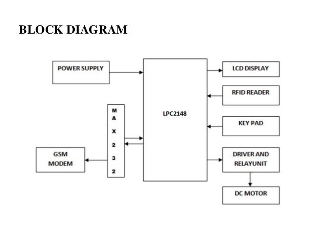
Rfid door lock block diagram.
Block diagram of the system node mcu.
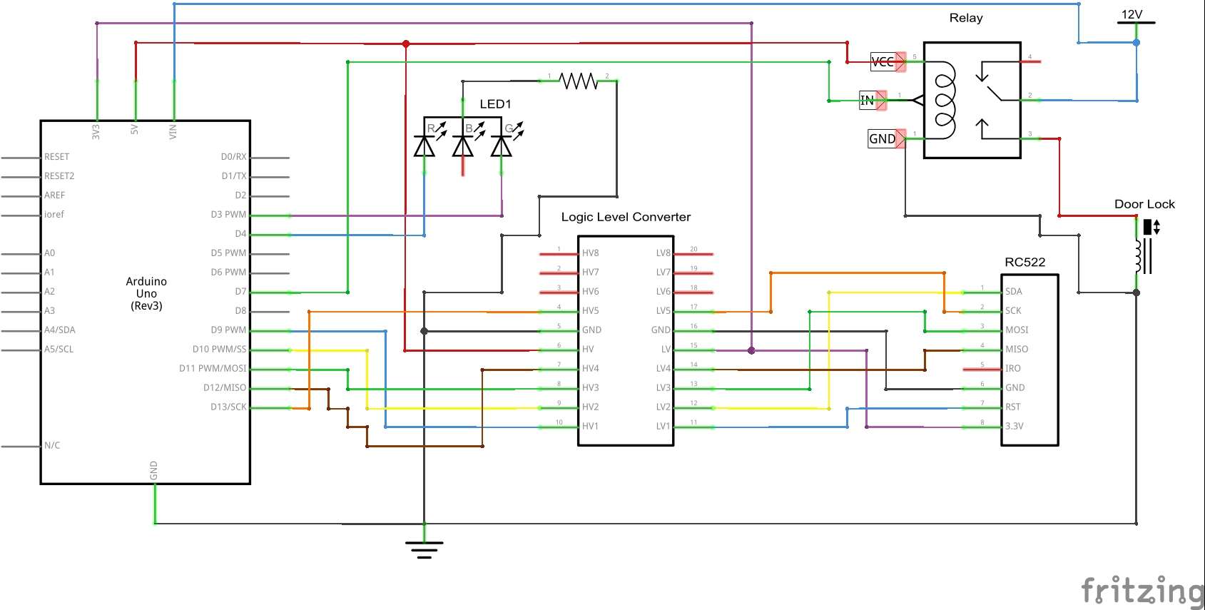
This system prevents a large destruction and loss the project is based on rfid rc522 module.
Rfid door lock can be made easily at your home and you can install it in any door.
Rfid and keypad door lock and alert system using arduino.
These door lock is just.
Rfid stands for radio frequency identification.
Em 18 rfid reader operates at 125 khz and it comes with an on chip antenna and it can be powered with 5v power supply.
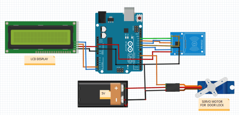
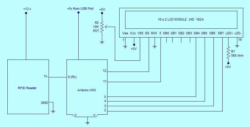
Lcd is used to display messages.
This rfid based security system is based on micro controller at89c52 and comprises a rfid module a lcd module for displaying the status and a relay for opening the door.
Secure your house by implementing this handy automatic door management system.
Any rfid system will consist of a rfid reader and a rfid tag.
Each rfid card has a unique id embedded in it and a rfid reader is used to read the rfid card no.
It provides serial.
It will contain a rfid reader writer and a magnetic door lock for simple use.
Level 1 block diagram 10.
The automatic door lock system circuit diagram using an arduino is shown below.
Glowing of caution led means that you are using the wrong tag.
The rfid door lock is a lock that is simple to install and allows the user to easily lock and unlock doors.
It closes manually after five seconds.
Arduino rfid door lock circuit diagram.
The tag near to rfid reader.
Rfid based door automatic management systemarduino rfid module rc522 simple project.
Glowing of led indicate that the lock is open.
Fig 1 shows a user trying to open the door by placing an rfid tag near the rfid reader.
Level 0 block diagram 7 2.
Nodemcu is an open source firmware and development kit that helps you to prototype or build iot.
If tag id matches with the id in the code lock will open for five seconds.
Rfid door locks and rfid attendance system are very popular now days and many hotels provide provide rfid tag to their customer to lock and unlock the door.
Arduino uno is the brain of this project.
This project can be enhanced by connecting an lcd display to display the outputs.
Flow chart of the system.
The tag will often be small and portable with little to no electronics in it.
Don t know about rfid rc522 module i will explain later.